A 1972 db Magazine article written by Eventide co-founders Richard Factor and Stephen Katz begins:
The audio professional recently has become aware of a new audio processing device, the so-called delay line. Various claims are made of its efficacy. It is alleged to multiply strings and voices, make possible greatly improved p.a. setups, and generate more realistic echos.

Prior to 1971, all electronic audio devices were analog. Studios worldwide employed tape machines, amps, compressors, and EQs that were built using only analog components – transistors, resistors, inductors, and capacitors. Integrated circuits were still in their infancy. Analog electronics could deliver nearly every audio effect with the exception of delay and reverb.
Delay was achieved using tape machines. Running a tape machine at 7.5 IPS, short delays were possible. Longer delays required the use of a pair of tape machines placed several feet apart with the tape spooled from the first machine (recording) to the second machine (playback). The time that it took the tape to travel from one machine to the next determined the delay.
Reverb was first accomplished by dedicating an empty room outfitted with a speaker and microphone – ‘the echo chamber’. By the 1960s, studios were installing plate reverbs and decommissioning their echo chambers. Plate reverbs were built using a large sheet of metal with transducers affixed. The sound of the reverb generated was a bit ‘metallic’ but had high density, high diffusion and was used widely. Compared to an echo chamber the primary shortcoming of plate reverbs was the fact that the onset of reverb was nearly instantaneous, unlike a ‘real’ space which had a pre-delay before the onset of reverb. Studios used tape delays to feed the audio to the plate reverb to introduce a pre-delay.
Integrated Circuits
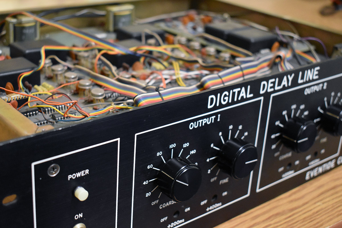
By 1971, integrated circuits (ICs) had advanced to the degree that it became practical to fabricate components with up to a thousand transistors on a single ‘chip’. The very first type of IC with thousands of transistors was the shift register. The shift register is a simple device with an input, an output, and a clock. Inside the shift register were 1,000 simple transistor circuits connected in series. One bit at a time is clocked into the shift register and with each clock ‘tick’ the bit is transferred, one step at a time, until the bit traverses all 1,000 steps and appears at the shift register’s output. The shift register is, in a sense, a primitive form of memory but unlike a RAM (random access memory), the shift register doesn’t store the data but simply delays it. Bits go in and, 1,000 clock ticks later, they come out. Perfect for a digital delay but not useful for anything more than that. The DDL 1745 circuit board held a field of shift registers connected in series.

Inside the DDL 1745


DDL 1745 Shift Registers
Of course, in order to build a digital delay line, the input audio signal had to first be converted to a digital representation and, at the output, converted back from its digital representation to its analog form. DACs (Digital to Analog Converters) are rather simple devices – basically resistor networks built with a set of resistors whose values were related by a factor of 2. ADCs (Analog to Digital Converters) on the other hand are more complicated and, in 1971, there were no commercially available ADCs suitable for converting high-quality audio. We used a design with a very high-frequency clock, counters, and a voltage comparator to create a guaranteed-monotonic converter, along with DBX dynamic range expansion. As a result, the audio quality was excellent.
Inside the DDL 1745 – Analog to Digital and Digital to Analog Boards
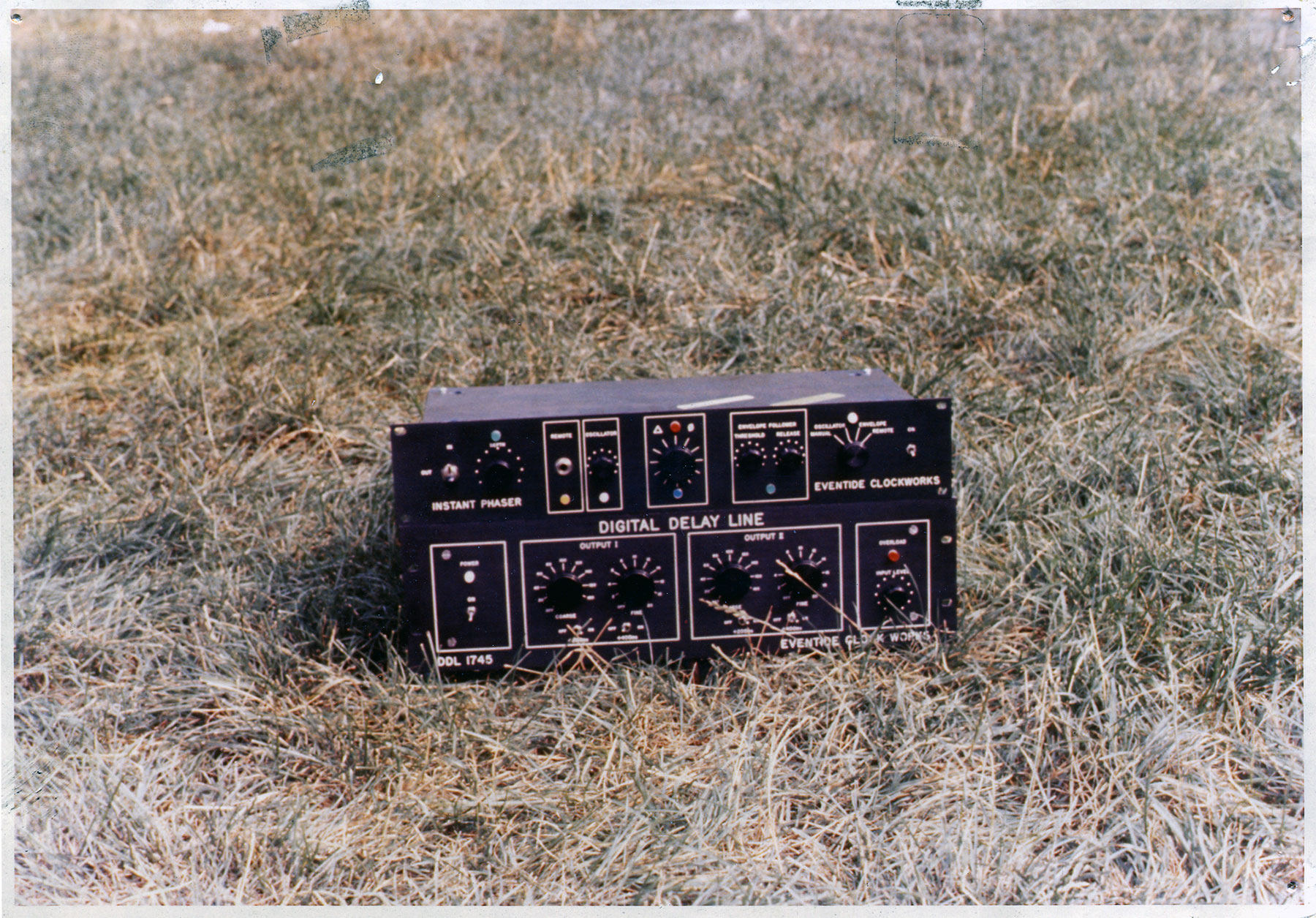
Eventide’s first model DDL (Digital Delay Line), the DDL 1745, used 100 shift registers connected in series with the shift registers clock at a rate which resulted in each shift register delaying audio by 2 msec. The DDL 1745’s total maximum delay was 200 msec. The user could adjust the delay in 2 msec steps. To achieve this delay the DDL contained on the order of a hundred thousand transistors. For reference, today’s iPhone has ~2 Billion transistors.
The DDL 1745 design also predated the commercial availability of LEDs and instead used incandescent bulbs!
As soon as the first DDL 1745s became available studios used them to replace tape delays for double tracking and as pre-delays feeding plate reverbs. Creative engineers and producers also used them to create comb filter tonal effects. The original DDL 1745 sold for $3,800 in 1972, which equals approximately $22,500 today.
The DDL 1745 at Watkins Glen Summer 1973 – First use of delay for sound reinforcement
When the first big outdoor festival/concerts like Woodstock were held, the PA folks encountered a somewhat unexpected problem. With a crowd so large, the normal array of speakers around the stage wouldn’t be enough, no matter how loud they were. To get the best sound to the back of the crowd, speaker towers needed to be constructed a few hundred feet away from the stage.
While this solved the problem of volume to the back of the crowd it created another: Sound travels through the air at 1100 ft/sec. That means the sound coming from the stage takes a while to get to your ears. If you (and the tower) are 250 ft from the stage, the sound from the speakers on the stage takes 250 msec (¼ sec) to reach your ears while you hear the sound from the tower speakers immediately, creating an annoying echo effect. This is due to the path the sound is taking to your ears. The feed to the speakers on the towers from the power amps is electrical. Electricity travels at the speed of light, so the sound coming from the tower speakers gets there instantly – no delay. The sound coming from the speakers on the stage is traveling through the air, so it arrives ¼ of a second later.
Eventide worked with The Grateful Dead’s live sound team, lead by Dan Healy, to install six DDL 1745s in the audio path to the two sets of speaker towers located hundreds of feet from the stage. Here’s a photo of the DDLs sitting next to the console in the sound booth.


Models 1745, 1745A, 1745M


Like the 1745, the 1745A used shift registers. The main difference was the front panel. By 1973, LEDs had become commercially available and a 7 segment LED was designed into the front panel. So instead of using big switches with screened legends on the front panel, the delay was selected by spinning a knob (turning a Richard Factor home-brewed optical encoder) and the delay time was displayed with numbers that lit up (LEDs). For studios that installed the 1745A, it was the first time a digital ‘read out’ appeared in their racks.
A couple of years later, with the rapid advance of semiconductors, memory chips with densities of 4kbits became available. RAMs (Random Access Memory) made it possible to do much more than simply shift a digital bit through a bunch of shift registers. By being able to actually ‘store’ bits by writing and reading from an addressable location, a wide range of delay-based effects became possible. The DDL 1745M (“M” for memory) was able to delay audio with much finer resolution and to vary delay relatively smoothly which also made pitch change possible. The 1745 was designed as a modular unit and a primitive pitch change module was made available as an option.
DDL 1745 Images


DDL 1745 in dB Magazine 1972


Eventide Clockworks Price List 1972

Related Content
50th Flashback #2.1: The DDL 1745
1745 Digital Delay Inducted into NAMM TECnology Hall of Fame
Remembering the Watkins Glen Festival
Documentation


